Observation and Analysis of Sand Casting
Casting is a processing method in which metallic materials are melted, poured into moulds, and then hardened into target shapes as they cool. This section introduces examples of observation and analysis of sand casting.
- Typical Casting Methods
- Types and Characteristics of Sand Casting
- Typical Casting Defects
- Examples of Observation and Analysis of Sand Casting Using a Digital Microscope
Typical Casting Methods
Typical casting methods include the following.
- Sand casting
- Mould type: Sand
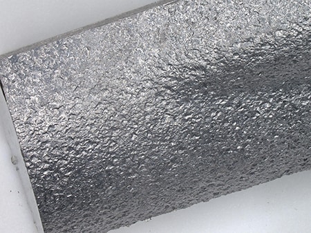
The oldest casting method. Melted metal is poured into a sand mould. Moulds can only be used once but the cost to make them is low, so this method is suitable for small lot production. The surfaces of parts made with sand moulds are rough because of the sand particles of the mould. Also, the accuracy is not particularly high. - Die casting
- Mould type: Metal
In this casting method, melted metal is injected into a metal mould under high pressure. Metal moulds are expensive but can be used repeatedly, so this method is suitable for mass production. Surfaces of die cast parts are smooth, and highly accurate products can be manufactured quickly. - Permanent mould casting
- Mould type: Metal
Melted metal is poured under only the force of gravity, without applying pressure. This method is called gravity casting or gravity die casting. Cast products using this method have high dimensional accuracy and excellent mechanical characteristics, so this method is suitable for parts that require high strength. - Lost-wax casting
- Mould type: Plaster, ceramic
Melted wax is poured into a mould to make a wax model. The model is covered with plaster or ceramic. It is baked in a furnace to melt the wax. The wax melts and runs out, leaving a space in the baked plaster or ceramic which becomes the mould. Moulds can only be used once but the cost to make them is low, so this method is suitable for small lot production. The surfaces of lost-wax cast parts are smooth, so highly accurate products can be manufactured.
Types and Characteristics of Sand Casting
Advantages and disadvantages of sand casting
- Advantages
- Wooden patterns require low initial investment.
- Wooden patterns can be produced quickly.
- Various shapes can be moulded, which allows for casting of complex and large products.
- Suitable for small-volume manufacturing of many product types
- Any metal material can be cast. (Die casting can use only non-ferrous metals such as aluminium alloys, zinc alloys, and magnesium alloys.)
- Disadvantages
- Low dimensional accuracy
- Casting surfaces are coarse due to the sand moulds.
- Running costs are high because the sand moulds are destroyed each time, so this method is not suitable for mass-production.
- Lower mechanical characteristics when compared to permanent mould casting due to low cooling speed
Types of sand moulds
The various types of sand mould are differentiated by the bonding method employed. The two most common sand mould types are:
- Green sand mould
- Clay (bentonite) is added to silica sand and the binding strength of water is used to bond the sand mould. Silica sand is cheap because it is produced naturally, but it is not suitable for mass-production.
- Shell mould
- A sand-resin mixture produced by mixing thermosetting phenolic resin with silica sand is used. This type of mould is called a shell mould because the mould is thin like a shell.
Thin shell moulds form smooth surfaces and are often used for precise casting of automotive engine parts and similar parts. Shell moulds can be destroyed easily, which makes them suitable for mass-production. However, they are more expensive when compared to green sand moulds because metal patterns must be used.
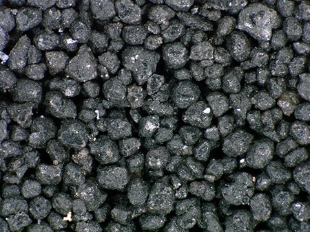
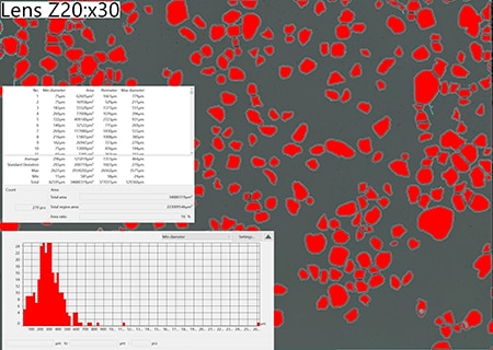
Sand particle size
The sand particle size greatly affects casting surfaces.
Smaller sand particles form smoother casting surfaces, but they hinder air flow and can confine gases which can result in defects. Larger sand particles form coarse casting surfaces, but they facilitate air flow and thus can produce castings with fewer defects caused by gases.
The sand particle size should be selected according to the needs of the application.
Typical Casting Defects
Typical casting defects include the following.
- Shrinkage cavity
-
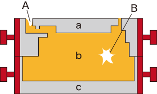
- A: External shrinkage cavity
- B: Shrinkage cavity
- a: Upper mould
- b: Core
- c: Lower mould
A shrinkage cavity is a type of cavity. Shrinkage cavities are relatively large complex-shaped hollows that occur inside of cast objects due to volumetric shrinkage when objects change from liquid to solid.
- Blowhole
-
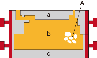
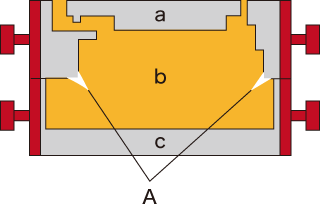
- A: Blowholes
- a: Upper mould
- b: Core
- c: Lower mould
Blowholes are another type of cavity. Blowholes are roundish hollows in cast objects. Melted metal includes air or other gases when it is poured into moulds, which causes blowholes.
- Crack
-
- A: Cracks
- a: Upper mould
- b: Core
- c: Lower mould
Cracks are fissures that occur on the surface of cast objects. Cracks occur due to the stresses that remain due to volumetric shrinkage or other causes during casting.
- Misrun
- A misrun occurs when a mould cavity fails to be filled all the way with molten metal, resulting in an incomplete cast product shape.
- Burr
- Burrs occur along matching surfaces (parting surfaces). Mould accuracy defects, incorrect assembly, and enlarged clearance due to deterioration are common causes of burrs.
- Dimension defect
- Moulds are made with consideration to volumetric shrinkage or deformation during casting. Incorrect expectations, mould dimension defects, or incorrect assembly can cause this problem.
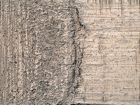
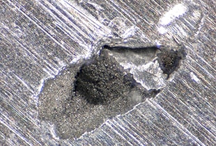
- Casting surface defect
- Casting surface defects occur when the sand of a mould surface melts and burns onto the cast product surface.
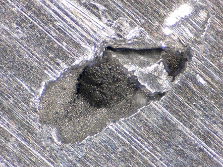
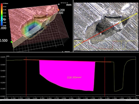
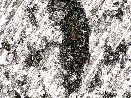
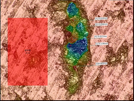
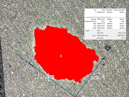
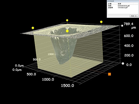
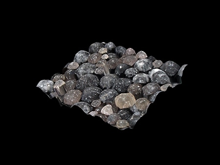
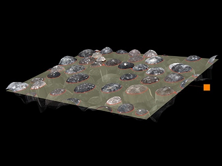
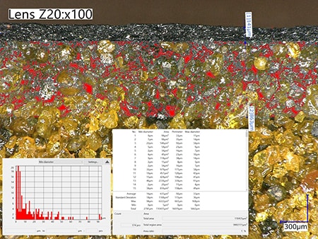
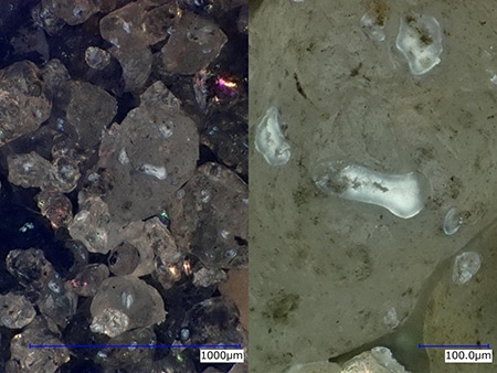
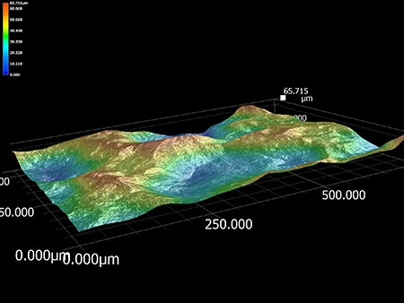
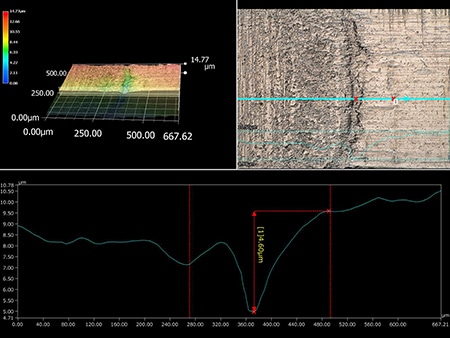
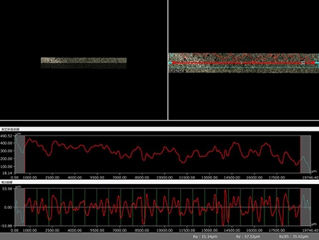
Examples of Observation and Analysis of Sand Casting Using a Digital Microscope
The latest examples of observation and analysis of sand casting using KEYENCE’s VHX Series 4K Digital Microscope are introduced below.