Observation and Measurement of Sintered Parts Using Digital Microscopes
Sintered parts are manufactured by forming metallic or ceramic powders in metal moulds and then baking and hardening the moulded parts at temperatures lower than their melting points. The advantages of sintering are that only a small amount of energy is required with minimum material losses and no time and effort are required for secondary processing because metals do not need to be melted. This section provides an overview of sintering and introduces observation and measurement examples of sintered parts using digital microscopes.
- Advantages and Disadvantages of Sintering
- Principle of Sintering
- Sintering Flow
- Observation and Measurement Examples of Sintered Parts Using Digital Microscopes
Advantages and Disadvantages of Sintering
Sintering is used to manufacture various parts because materials do not need to be melted.
- Advantages of sintering
-
- Almost any material can be used as long as it can be powdered.
- Secondary processing is not required in many cases.
- Material losses are small.
- Complex shapes can be moulded.
- Materials can be freely mixed.
- Sintered parts are porous and thus light.
- Even materials with high melting points can be processed.
- Disadvantages of sintering
-
- Powders are processed, which increases the material costs.
- Parts shrink when sintered.
- Mechanical properties, such as strength, are inferior to those produced by casting or pressing.
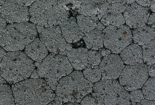
Principle of Sintering
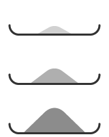
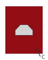
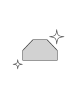
Solid powder surfaces are unstable because atoms, molecules, and ions are not bonded. Joints called necks are formed when solid powders are heated. As atoms, molecules, and ions move (diffuse) from powder particle surfaces to necks, necks become larger and the surface areas decrease. As necks continue to grow through the initial, intermediate, and final stages, density increases and the sinter is completed.
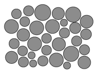
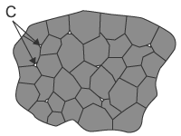
- A: Neck
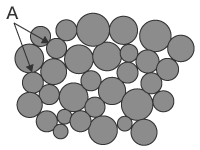
- B: Open pores
- C: Closed pores
Pores that are connected to external air are called open pores and those isolated in an object are called closed pores.
Sintering Flow
- Determine the mixing ratio of material powders and mix them with a mixier until the mixture becomes uniform.
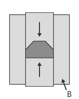
- Put the powder mixture into a metal mould and form it with a press.
- Heat the moulded part in a sintering furnace for several hours.
Material powders do not melt because the moulded part is baked to harden at temperature lower than their melting points. Material powders are firmly bonded to each other when heated for a long time and become a sinter.
Sintering furnaces are filled with gases to prevent sinters from becoming oxidised.
Sinters may be cut or polished to increase accuracy or heat-treated to increase hardness.
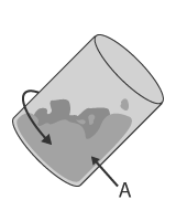
- A: Mixer
- B: Press
- C: Sintering furnace
Observation and Measurement Examples of Sintered Parts Using Digital Microscopes
These are the latest examples of observation and measurement of sintered parts using KEYENCE’s VHX Series 4K Digital Microscope.
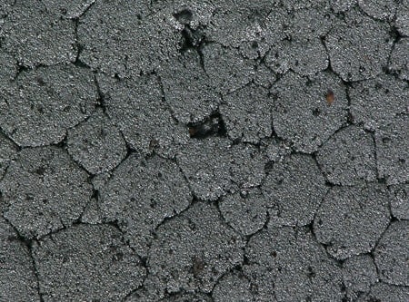
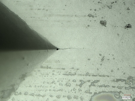
Low particle boundary density (low strength)
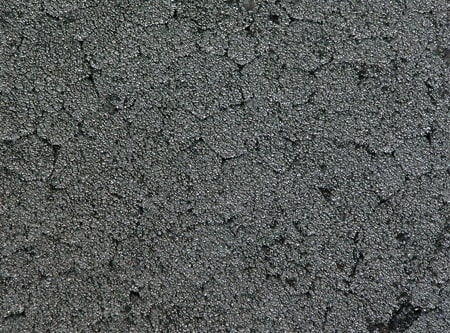
High particle boundary density (high strength)

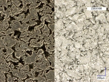
Left: With the attachment/Right: Without the attachment
Using the adjustable illumination attachment allows for pores to be observed clearly.
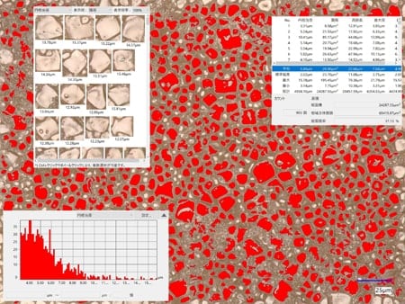
The grains used to be visually counted by size using a scanning electron microscope (SEM). This process can now be done automatically using the automatic area measurement function.
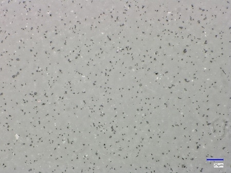
Before measurement
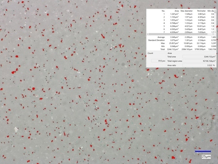
Automatic area measurement image
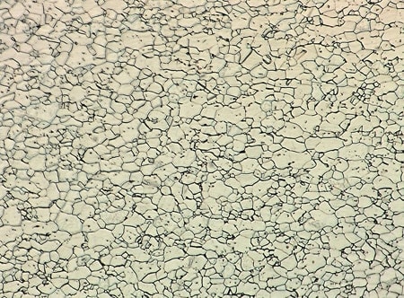
Before measurement
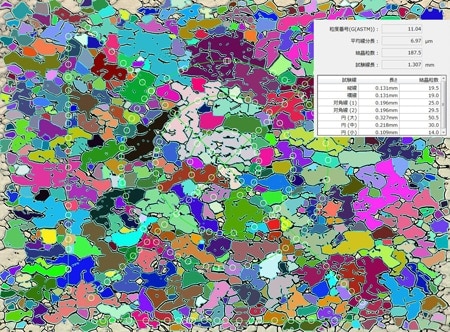
Automatic area measurement (grain size analysis) image
The automatic area measurement function allows for accurate grain size analysis, significantly reducing the amount of analysis work.

