Observation and Measurement of Wire Bonding Using a Digital Microscope
The spread of 5th generation mobile communication systems (5G) has led to semiconductor devices becoming smaller and more integrated, and has also increased demand for product inspection and analysis.
This section introduces examples of observation and measurement of wire bonding, a common observation target for digital microscopes.
- Typical Bonding for IC Chip Mounting
- Wire Bonding Flow
- Example of Observation and Measurement of Wire Bonding Using a Digital Microscope
Typical Bonding for IC Chip Mounting
- Wire bonding
-
Wire bonding is used to connect semiconductor chip electrodes to the electric conductors of lead frames or boards with thin wires of gold, aluminium, or copper.

- Flip-chip bonding
-
The method where IC chips are attached directly to a PCB is called FC-BGA (Flip Chip-BGA). Bumps are made on the electrodes of an IC chip and then connected to the electrodes of a PCB. This saves space, compared to wire bonding.
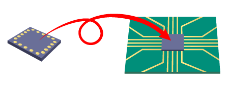
- Left: IC chip
- Right: Flip (face down)
Wire Bonding Flow
-
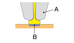
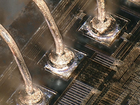
1. A tube-shaped capillary (like an injection needle) with a metal wire running through it is used. The wire tip is sparked with high voltage to make it round, and then the round part is bonded to the electrode. This is called ball bonding or 1st bonding. The load from the capillary, ultrasonic waves, and heat from the bonding stage allow for bonding to take place.
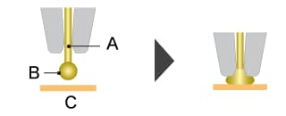
- A: Gold wire
- B: Ball
- C: IC chip
-
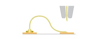
2. While the capillary is moving to the 2nd bonding point after the 1st bonding, the bonding wire is continuously pulled out to form a loop with the movement of the capillary.
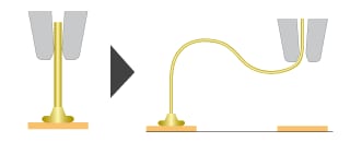
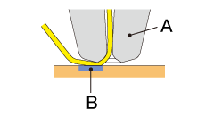
- 3. When connecting to a lead electrode, no ball is made and the wire is mashed by the capillary. This is called stitch bonding or 2nd bonding.
-
4. The wire clamper is closed to clip the metal wire, and then the capillary is lifted to cut the wire.
Capillary tip part names
- A: Capillary
- B: Bonding part
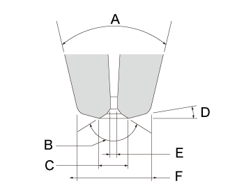
- A: Cone angle
- B: Chamfer angle
- C: Chamfer diameter
- D: Face angle
- E: Hole diameter
- F: Tip diameter
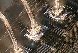
Example of Observation and Measurement of Wire Bonding Using a Digital Microscope
The latest examples of observation and measurement images of wire bonding using KEYENCE’s VHX Series 4K Digital Microscope are introduced below.
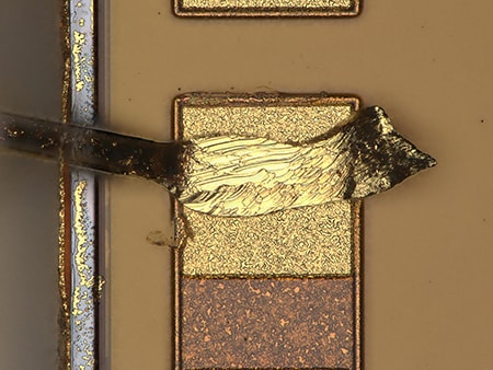
1000×, coaxial illumination
The depth composition function allows for easy focusing even at high magnification.
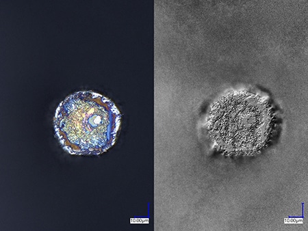
1000× Left: coaxial illumination,
right: Optical Shadow Effect Mode image
Optical Shadow Effect Mode allows for clear observation of fractured uneven surfaces.
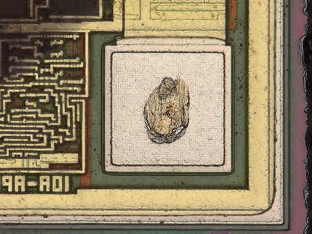
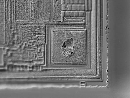
1000×, Optical Shadow Effect Mode image
Optical Shadow Effect Mode allows for clear observation of fractured uneven surfaces.

