Programmable Controller
KV-7000 series
Specs Programmable Controller KV-7000 series
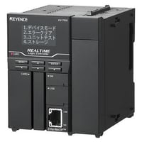
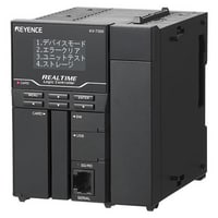
CPU unit
|
Model |
KV-7500 *1 |
KV-7300 *1 |
|||
|
Image |
|
|
|||
|
Type |
CPU unit |
||||
|
General specifications |
Power voltage |
KV-5000/3000 Series System configuration using an expansion unit: 24 VDC (±10 %) |
|||
|
Operating ambient temperature |
KV-5000/3000 Series System configuration using an expansion unit: 0 to +50 °C (No freezing) |
||||
|
Operating ambient humidity |
KV-5000/3000 Series System configuration using an expansion unit: 10 to 95 % RH (No condensation) |
||||
|
Ambient temperature for storage |
KV-5000/3000 Series System configuration using an expansion unit: -20 to +70 °C |
||||
|
Storage relative humidity |
KV-5000/3000 Series System configuration using an expansion unit: 10 to 95 % RH (No condensation) |
||||
|
Operating environment |
No dust or corrosive gas |
||||
|
Altitude |
2,000 m or less |
||||
|
Noise immunity |
1,500 Vp-p or more, Pulse width: 1 µs, 50 ns (based on noise simulator), IEC standard-compliant (IEC 61000-4-2/3/4/6) |
||||
|
Withstand voltage |
1,500 VAC for 1 minute (between the power terminals and the I/O terminals, and between the external terminals and the housing) |
||||
|
Insulation resistance |
50 MΩ or more (between the power terminals and the I/O terminals, and between the external terminals and the housing, with 500 VDC megohmmeter) |
||||
|
Shock resistance |
Acceleration: 150 m/s2, Operation time: 11 ms, 2 times in each of the X, Y, and Z directions |
||||
|
Pollution degree |
2 |
||||
|
Vibration resistance |
Intermittent vibration |
Frequency 5 to 9 Hz |
Half amplitude: 3.5 mm*2 |
||
|
Frequency 9 to 150 Hz |
Acceleration: 9.8 m/s2*2 |
||||
|
Continuous vibration |
Frequency 5 to 11 Hz |
Half amplitude: 1.75 mm*2 |
|||
|
Frequency 9 to 150 Hz |
Acceleration: 4.9 m/s2*2 |
||||
|
Performance specifications |
Arithmetic control mode |
Stored program mode |
|||
|
I/O control mode |
Refresh mode |
||||
|
Program language |
Expanded ladder, KV Script, mnemonic |
||||
|
Number of commands |
Basic instruction: 80 classes, 181 instructions |
||||
|
Instruction execution speed |
Basic instruction: Min. 0.96 ns |
||||
|
CPU memory capacity |
64 MB |
21 MB |
|||
|
Program capacity |
Approx. 1,500k steps |
Approx. 160k steps |
|||
|
Maximum number of units to be installed |
16 units (only with KV-7000 Series expansion unit) |
||||
|
Maximum number of I/O points |
Maximum 3,072 points for expansion (KV-EB1S/KV-EB1R: 2 units used, 64-point unit used) |
||||
|
Bit device |
Input relay R |
Total 16,000 points 1 bit |
|||
|
Output relay R |
|||||
|
Internal auxiliary relay R |
|||||
|
Link relay B |
32,768 points 1 bit |
||||
|
Internal auxiliary relay MR |
64,000 points 1 bit |
||||
|
Latch relay LR |
16,000 points 1 bit |
||||
|
Control relay CR |
1,280 points 1 bit |
||||
|
Word device |
Timer T |
4,000 points 32 bits |
|||
|
Counter C |
|||||
|
Data memory DM |
65,535 points 16 bits |
||||
|
Expansion data memory EM |
|||||
|
File register |
Current bank FM |
524,288 points 16 bits |
|||
|
Dial mode ZF |
|||||
|
Link register W |
32,768 points 16 bits |
||||
|
Temporary data memory TM |
512 points 16 bits |
||||
|
Index register Z |
12 points 32 bits |
||||
|
Control memory CM |
6,000 points 16 bits |
||||
|
Device comment |
Approx. 224,000 |
Approx. 102,000 |
|||
|
Label |
Approx. 285,000 |
Approx. 131,000 |
|||
|
Power failure hold function |
Program memory |
Flash ROM can be written 10,000 times |
|||
|
Device |
Nonvolatile RAM |
||||
|
Calendar timer |
Backup condenser lasts approx. 15 days (25 °C) |
||||
|
Self-diagnosis function |
CPU error, RAM error, other |
||||
|
Internal current consumption |
200 mA or less |
||||
|
Weight |
CPU unit: Approx. 270 g |
||||
|
*1 This product is not available for sale in China and cannot be ordered for shipment to China. |
|||||
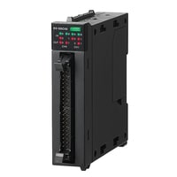
High-speed I/O unit
|
Model |
KV-SIR32XT*1 |
|||
|
Image |
|
|||
|
Type |
High-speed I/O unit |
|||
|
External connection mode |
Connector (MIL standard)*2 |
|||
|
Input |
Number of inputs |
32 points |
||
|
Input mode |
24 VDC mode, 5 VDC mode*3 (Overvoltage protection function included*4) |
|||
|
Max. input voltage |
24 VDC mode: 28.8 VDC, 5 VDC mode: 6.0 VDC |
|||
|
Rated input voltage |
24 VDC mode: 24 VDC 5.1 mA, 5 VDC mode: 5 VDC 8.8 mA |
|||
|
Min. ON voltage |
24 VDC mode: 19 V, 5 VDC mode: 3.5 V |
|||
|
Max. OFF current |
24 VDC mode: 1.5 mA |
|||
|
Max. OFF voltage |
5 VDC mode: 1.5 V |
|||
|
Common point mode |
16 points/1 common point (2 terminals)*5 |
|||
|
Input time constant |
1 µs/10 µs/20 µs/100 µs/500 µs/1 ms/5 ms/10 ms/50 ms |
|||
|
Input impedance |
24 VDC mode: 4.4 kΩ, 5 VDC mode: 350 Ω |
|||
|
Output |
Number of outputs |
32 points |
||
|
Output form |
MOSFET (N-ch) (with overcurrent protection function)*6 |
|||
|
Rated load |
30 VDC 0.2 A (1.6 A/1 common point) |
|||
|
Leak current at OFF |
100 µA or less |
|||
|
Residual voltage at ON |
0.5 VDC or less |
|||
|
Common point mode |
16 points/1 common point (2 terminals)*5 |
|||
|
Operating time |
OFF to ON: 1 µs or less (Load: 5 mA to 200 mA) |
|||
|
Internal current consumption |
130 mA or less |
|||
|
Weight |
Approx. 190 g |
|||
|
*1 For KV-8000/KV-7000 Series |
||||
High-speed analogue input unit
|
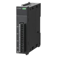
Model |
KV-SAD04*1 |
|||
|
Image |
|
|||
|
Type |
High-speed analogue input unit |
|||
|
Analogue input point |
4 points (differential input) |
|||
|
Analogue input range (resolution) |
Voltage |
-10 to +10 V (0.5 mV 1/40,000) |
||
|
Input current |
0 to 20 mA (1 µA 1/20,000) |
|||
|
Input impedance |
Voltage: 1 MΩ, Current: 250 Ω |
|||
|
Conversion speed |
10 µs/ch |
|||
|
Conversion precision |
25 °C ±5 °C: ±0.1 % (±20 digit) |
|||
|
Insulation mode |
Between unit and CPU: Photocoupler insulation, non-insulation between channels |
|||
|
Absolute max. input |
Voltage: -15 V to +35 V, Current: 30 mA |
|||
|
Internal current consumption |
80 mA or less |
|||
|
Weight |
Approx. 130 g |
|||
|
*1 For KV-8000/KV-7000 Series |
||||
High-speed analogue output unit
|
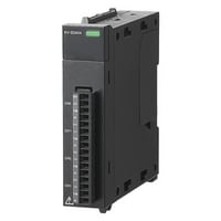
Model |
KV-SDA04*1 |
|||
|
Image |
|
|||
|
Type |
High-speed analogue output unit |
|||
|
Analogue output points |
4 points |
|||
|
Analogue output range (resolution) |
Voltage |
-10 to +10 V (0.5 mV 1/40,000) |
||
|
Input current |
0 to 20 mA (1 µA 1/20,000) |
|||
|
Conversion speed |
10 µs/ch |
|||
|
Conversion precision |
25 °C ±5 °C: ±0.1 % (±20 digit) |
|||
|
Insulation mode |
Between unit and CPU: Photocoupler insulation, non-insulation between channels |
|||
|
Min. load resistance |
Voltage: 1 kΩ |
|||
|
Max. load resistance |
Current: 500 Ω |
|||
|
Internal current consumption |
170 mA or less |
|||
|
Weight |
Approx. 140 g |
|||
|
*1 For KV-8000/KV-7000 Series |
||||
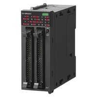
Positioning/Motion unit
|
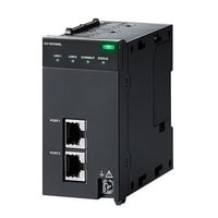
Model |
KV-XH16ML*1 |
KV-XH04ML*1 |
|||
|
Image |
|
|
|||
|
Type |
Positioning/Motion unit |
||||
|
Number of control axes |
16 axes (total including a virtual axis) |
4 axes (total including a virtual axis) |
|||
|
Built-in device |
Relay: 2,112 points (132 ch), data memory: 4 words |
Relay: 576 points (36 ch), data memory: 4 words |
|||
|
Output format |
MECHATROLINK-III |
||||
|
Connectable CPU units |
KV-8000/KV-7500/KV-7300 |
||||
|
Refreshes |
Automatic refresh, direct refresh, inter-unit synchronisation refresh |
||||
|
Control mode |
Position control, Torque control, Speed control, ML-III command, I/O control |
||||
|
Control period |
From 62.5 µs (from 125 µs when using the SV2 Series) |
From 500 µs |
|||
|
Starting time |
125 µs |
500 µs |
|||
|
Axis control function execution method |
Ladder program, unit program (flow, C language) |
Ladder program, unit program (flow) |
|||
|
Unit program capacity |
3 MB (max. number of blocks: approx. 20,000) |
||||
|
Flow |
Block Type |
Positioning control block, synchronisation control block, speed control block, torque control block,origin return block, current coordinate change block, speed change block, target coordinate change block,continuous positioning start block, continuous point number block, continuous independent/linearinterpolation block, continuous arc interpolation block, continuous positioning completion standby block,calculation block, standby block, program execution block, program stop/restart block,program forced end block, unit interrupt block, cam data reading/writing block, selection branch block,parallel branch block, merge block, GOTO block, start block, end block |
|||
|
Maximum number of flows |
256 |
||||
|
Number of simultaneous activities |
Unlimited |
||||
|
Internal data memory |
524,288 words |
||||
|
Position unit |
mm, deg (angle), PLS (pulse count), decimal place 0 to 9, unit conversion function available |
||||
|
Cumulative address |
-2,147,483,648 to +2,147,483,647 instruction units |
||||
|
Positioning control |
Positioning mode |
Absolute value/relative value |
|||
|
Position setting range |
-2,147,483,648 to +2,147,483,647 instruction units |
||||
|
Interpolation |
Linear interpolation (up to 16 axes), arc interpolation, helical interpolation |
||||
|
Single operation address |
-2,147,483,648 to +2,147,483,647 instruction units |
||||
|
Acceleration/deceleration curve |
Straight-line, SIN |
||||
|
Acceleration/deceleration time |
0 to 65,535 ms |
||||
|
M-code |
1 to 65,000, WITH/AFTER mode |
||||
|
Sensor positioning |
External input-based switching control from speed to position |
||||
|
Number of points |
100 points/axis (Trace control of 100 points or more using flows is also possible.) |
||||
|
Special functions |
Sync type follow-up control, absolute position follow-up control |
||||
|
Synchronisation control |
Input |
External reference, instruction coordinates, current coordinates |
|||
|
Input filter |
Reverse rotation protection function |
||||
|
Clutch |
Select from direct, slide, and following |
||||
|
Cam |
Resolution: 2,048 to 32,768, amount of data: 4 to 64 (number changes according to the resolution) |
||||
|
Correction during operation |
Correction via auxiliary input, phase correction, and lead angle correction |
||||
|
Origin return |
Origin return method |
Data set type, Dog type (push), Dog type ("With Z phase" or "Without Z phase" can be selected), |
|||
|
JOG/inching |
JOG (high speed/low speed), inching (number of pulses can be specified) |
||||
|
Teaching |
Current coordinate teaching |
||||
|
Memory data |
Point parameters (each axis), synchronisation parameters (each axis), cam data, unit program, |
||||
|
Output display |
LINK, CONNECT, error status |
||||
|
Self-diagnosis function |
Diagnosis can be made through hardware error, various parameter errors, error number, and messages |
||||
|
Parameter setting |
Parameters can be set from KV STUDIO, ladder programs, and unit programs |
||||
|
Data backup |
Coordinates: Nonvolatile memory backup (unlimited) |
||||
|
Internal current consumption |
400 mA or less |
160 mA or less |
|||
|
Weight |
Approx. 280 g |
Approx. 190 g |
|||
|
*1 For KV-8000/KV-7000 Series |
|||||
High-speed positioning unit
|
Model |
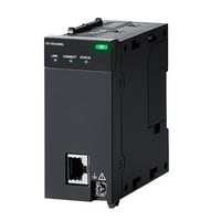
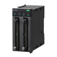
KV-SH04PL*1 |
|||
|
Image |
|
|||
|
Type |
High-speed positioning unit |
|||
|
Number of control axes |
4 axes |
|||
|
Input |
Positive (negative) direction limit switch, origin sensor, stop sensor, continuous instant starting, 1 point per axis for 4 points in total, 24 VDC input possible |
|||
|
Output |
Pulse output (differential line driver): equivalent to AM26C31 (max. 20 mA) |
|||
|
Output frequency |
1 Hz to 8 MHz |
|||
|
Output format |
Differential line driver/open collector (switched per axis via hardware switch) |
|||
|
Control mode |
Standard mode, High-speed mode |
|||
|
Control period |
Standard mode: 500 µs, High-speed mode: 62.5 µs |
|||
|
Starting time |
Standard mode: From 500 µs, High-speed mode: From 8 µs (continuous instant starting: 1 µs) |
|||
|
Basic operation |
Standard mode: Origin return/JOG, straight-line interpolation (2 to 4 axes), position control (ABS/INC), speed control (+/- direction) |
|||
|
Functions |
Standard mode: |
|||
|
Position unit |
Standard mode: mm, deg (angle), PLS (pulse count) decimal place 0 to 9, unit conversion function |
|||
|
Positioning control |
Position setting range |
-2,147,483,648 to 2,147,483,647 |
||
|
Acceleration/deceleration curve |
Standard mode: Straight-line, SIN, High-speed mode: Straight-line |
|||
|
Acceleration/deceleration rate |
Acceleration/deceleration individual setting |
|||
|
Acceleration/deceleration time |
Standard mode: 0 to 65,535 ms |
|||
|
M-code |
0 to 65,000, WITH/AFTER mode |
|||
|
Number of points |
100 points/axis |
|||
|
Origin return |
Origin return method |
Dog type ("With Z phase" or "Without Z phase" can be selected by pushing the button), Dog type inching ("With Z phase" or "Without Z phase)*2, |
||
|
JOG/inching |
Inching (number of pulses can be specified)*2, JOG |
|||
|
Teaching |
Current coordinate teaching |
|||
|
24 V power input (I/O) |
24 VDC (-15 %/+20 %) |
|||
|
5-V power output |
5 VDC (±10 %), 200 mA or less |
|||
|
Other functions |
Multi-axis simultaneous starting based on unit interrupt/inter-unit synchronisation |
|||
|
Internal current consumption |
200 mA or less, external I/O: 260 mA or less |
|||
|
Weight |
Approx. 230 g |
|||
|
*1 For KV-8000/KV-7000 Series |
||||
High-speed counter unit
|
Model |
KV-SSC02*1 |
|||
|
Image |
|
|||
|
Type |
High-speed counter unit |
|||
|
Input frequency |
4 MHz (16 MHz during 2-phase, 4 times multiplication) |
|||
|
Counting range |
32 bits |
|||
|
Number of channels |
2 ch |
|||
|
Mode |
Input selection |
External terminal (CH0, CH1), internal clock (0.05 µs, 1 µs, 10 µs, 100 µs), other CH coincidence output, |
||
|
Input mode |
1-pulse with/without direction, 2-pulse addition/subtraction operation, 2-phase 1X/2X/4X |
|||
|
Counting operation mode |
Up-down counting mode, Enable counting mode, Preset counting mode, |
|||
|
Counting mode |
Linear, ring |
|||
|
Frequency, revolution counter operation mode |
Frequency counting mode, revolution counter B mode (1-revolution time measurement) |
|||
|
Input |
Count input |
A-phase/B-phase/Z-phase (preset), 3 points for each channel, 6 points in total |
||
|
Control input |
Enable (also used for input capture) input, 1 point for each channel, 2 points in total 12 to 24 V DC input possible, photocoupler insulatio |
|||
|
Output |
Comparator coincidence output |
2 points for each channel, 4 points in total, photocoupler insulation |
||
|
Input capture function |
By external input (max. 4 points) |
|||
|
Buffering function |
Buffering period: 1 µs or longer |
|||
|
Input filter function |
Input time constant switching (6 types of counting/9 types of control) |
|||
|
Preset function |
Possible to select from preset (Z-phase) input and internal relay-based rising edge/falling edge/level (only when an external input is used) |
|||
|
Serial encoder communication function |
Supported encoder |
Absolute encoders that support EnDat2.2/22, BiSS (C-mode), and YASKAWA serial |
||
|
Communication cycle |
EnDat2.2/22: 50 µs, BiSS (C-mode): 50 µs, YASKAWA serial: 62.5 µs |
|||
|
Input |
Equivalent to a differential line receptor that meets the EIA RS485 standard |
|||
|
Output |
Equivalent to a differential line driver that meets the EIA RS485 standard |
|||
|
Encoder 5 V power |
5 VDC (±5 %), 300 mA or less |
|||
|
Other functions |
Unit interrupt, inter-unit synchronisation |
|||
|
Internal current consumption |
190 mA or less |
|||
|
Weight |
Approx. 130 g |
|||
|
*1 For KV-8000/KV-7000 Series |
||||